Modern preparation of a lenticular image is associated with digital interlacing, meaning the division of successive views into narrow strips and their arrangement according to the geometry of the lenticular sheet. In the past, the same fundamental relationship had to be achieved optically and mechanically. The camera changed position relative to the scene, while the lenticular screen moved in a precisely defined manner relative to the photosensitive material.
Patent documents describe two basic approaches: a direct method, in which the views were separated inside the camera, and an indirect method, which involved producing separate negatives and subsequently combining them while exposing the lenticular material. The first method is particularly interesting. It shows that before the era of digital processing, interlacing did not have to be a separate stage of image preparation—it could be created at the moment the photograph was taken.
A Screen Used Not Only for Viewing
A lenticular screen is an array of many parallel optical elements. In the finished image, it directs different parts of the composition in different directions, allowing the observer to see a different view depending on the position of their eyes or the viewing angle. In the direct method, however, it served an additional function: it participated in the actual recording of the image.
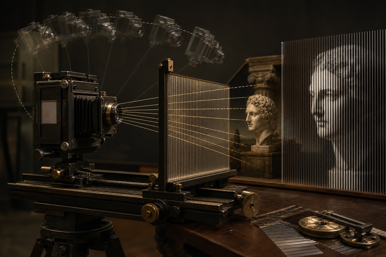
In the solution described in the patent documentation, the screen was located inside the camera, directly in front of the negative. During successive exposures, or during a single long exposure, it was moved laterally relative to the photosensitive material. At the same time, the camera changed its viewpoint. Light passing through the individual elements of the screen therefore reached the appropriate narrow areas of the negative.
In practice, the optics performed a task that can now be entrusted to software. Successive perspectives were not first recorded as complete images and only later divided into strips. Their fragments were directed immediately to the correct positions in a shared recording. This is an interpretation of the principle derived from the patent descriptions, not a claim that all historical lenticular processes worked identically.
Camera Movement as a Source of Parallax
Views showing the scene from different positions are required to create a sense of depth. The differences between them are called parallax. When the camera moves relative to the objects, their positions in relation to one another within the frame change: nearer and more distant elements shift relative to each other by different amounts.
One patent description of a scanning 3D camera provided for the camera to move along an arc. The center of this arc was located within a selected key subject in the scene. During the entire scan, the screen was to be shifted relative to the film by the width of one lenticule. These two movements—of the camera and of the screen—had to be synchronized.
Movement along an arc was not an arbitrary design choice. It allowed the camera to remain directed toward a specific part of the subject while the viewpoint changed. From the perspective of recording geometry, this meant controlling the position of a selected scene element even as the other planes changed their relative displacement. These differences were what provided the spatial information.
The Significance of the Key Subject
The documentation uses the term key subject matter, which can be understood as the key subject or a selected part of the scene serving as a reference point. The purpose of synchronizing the movement of the camera and the screen was to keep its image registered with a specific point of the lenticular system.
This does not mean that the entire scene remained stationary on the photosensitive material. If all its elements had maintained exactly the same position, the perspective differences required to reproduce depth would not have been created. The selected subject was stabilized, while other elements changed position depending on their spatial location.
This can be compared to maintaining one point in the frame as an optical anchor. This is an explanation of the mechanism, not a quotation from the documentation. The patents confirm the need to register the key subject relative to a selected point on the screen and to synchronize the movements.
Stepwise Exposures or Continuous Scanning
The direct method could use successive exposures made from different positions. After each shot, the position of the system had to be changed appropriately so that the next view would be recorded in different strips of the negative. The documentation also allowed for a single long exposure during which the movement took place continuously.
Both variants led to a similar goal but imposed slightly different mechanical requirements. In stepwise recording, precise positioning before each exposure was important. In continuous scanning, the consistency of movement speeds and ranges mattered. In both cases, a synchronization error changed the position at which a fragment of a given view reached the area beneath the screen.
The supplied materials do not make it possible to specify mechanical tolerances, exposure times, or the parameters of the photographic materials used. It can, however, be stated that the method depended on the controlled movement of several components and on maintaining their relative geometry.
The Bonnet Process: A Single Lens and Heavy Equipment
A historical description of the Bonnet process, cited by the Photographic Historical Society of Canada, presents a system using a single lens. It moved along an arc around part of the photographed subject. The plate and the lenticular selector remained parallel to the plane being photographed.
This is an important detail because it shows that recording multiple views did not require the simultaneous use of an array of lenses. Perspective variation could be achieved by moving a single optical system. The price, however, was the elaborate mechanism required to perform controlled movement.
According to the same historical description, recording 20 strip images per lenticule required a considerable range of camera movement. The device intended for such a camera sweep, meaning a controlled camera traverse, could weigh approximately half a ton. This information concerns the equipment cited, not every analog lenticular camera.
The weight of the device clearly illustrates the physical nature of the process. The precision that we now associate with calculations and pixel placement was achieved using guides, mounts, and mechanisms coupling the movements. The large size was not an end in itself, but a consequence of the adopted recording method.
The Indirect Method: Views Met Later
The indirect method was an alternative. Separate negatives were first produced from different viewpoints. They were then projected successively in an enlarger onto material used in conjunction with a lenticular screen. The views were therefore separated during a later exposure stage rather than directly inside the camera.
The difference between the two methods primarily concerns where the final arrangement of strips was created. In the direct approach, the scene, camera movement, screen, and negative belonged to a single recording process. In the indirect approach, the photography stage provided a set of separate images that were only later integrated optically.
In terms of workflow, the indirect method resembles later digital interlacing: there is a set of complete views, and combining them is a separate operation. This does not mean that the two processes are technically identical. The enlarger, photosensitive material, and screen formed an optical-photographic system, whereas modern interlacing can be performed on image data.
Why Synchronization Was Crucial
Direct lenticular photography combined several relationships in a single operation. The camera had to provide the correct change in perspective, the screen divided the light into strips, and the photosensitive material recorded successive fragments of the views. Every movement affected the other components.
The documents indicate the particular importance of three relationships:
- camera movement determined the change in viewpoint and the parallax of the scene,
- movement of the screen relative to the film determined the arrangement of the strips belonging to successive views,
- referencing the movement to the key subject helped maintain controlled recording geometry.
If this method is treated as a mechanical equivalent of interlacing, its requirements are easier to understand. It was not merely a matter of taking a series of photographs from different lateral positions. It was also necessary to ensure that each viewpoint was recorded beneath the appropriate part of the lenticular system.
Analog Interlacing Built into the Design
Moving cameras reveal a less obvious aspect of the history of lenticular imaging. A spatial image was not always created from finished photographs assembled at a later stage. In the direct method, the way in which the views were interlaced was built into the camera design and the exposure process.
The Bonnet process and the solutions described in the patents should not automatically be equated as a single, unchanging design. They nevertheless share a fundamental idea: the change in perspective was achieved through controlled movement, while the screen participated in assigning image fragments to the directions from which they would later be viewed.
Digital tools separated calculations from camera mechanics, but they did not eliminate the fundamental problem. The set of views still has to be correctly matched to the geometry of the screen. Early devices solved this task physically—by means of an arc of movement, a shift of one lenticule, optical registration, and heavy, precise equipment.