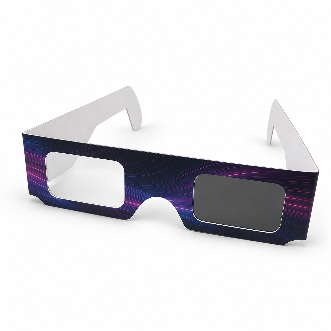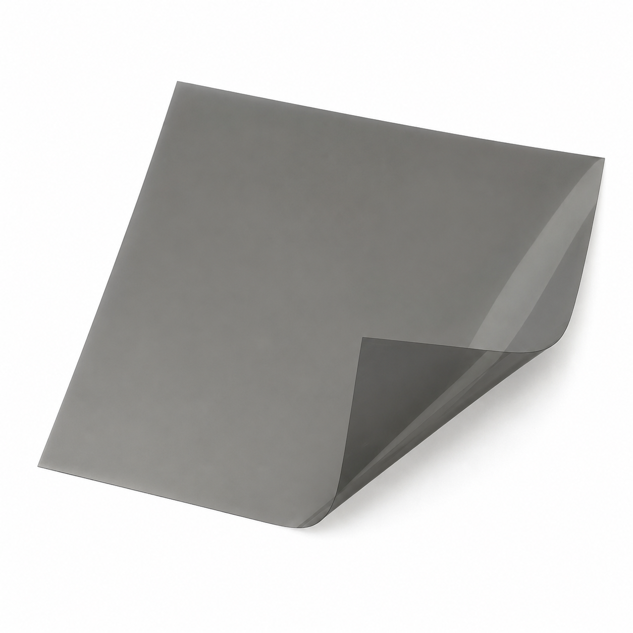
Unmarked polarizing film may look like an ordinary tinted sheet. Its most important property becomes apparent only when it is placed in the path of light with a specific polarization. No specialized optical setup is needed to perform a basic test: an LCD monitor can serve as the source of polarized light.
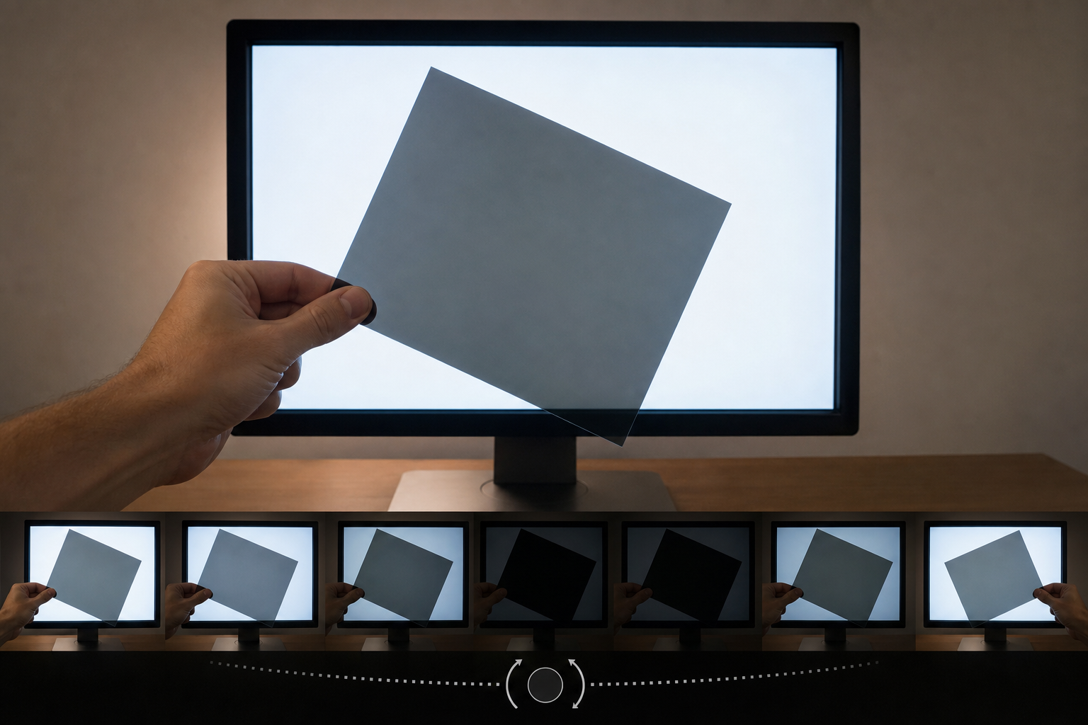
The experiment involves placing a linear polarizing filter in front of a bright screen and rotating it parallel to the plane of the display. Changes in brightness make it possible to find two characteristic orientations: maximum transmission and greatest extinction. This is a qualitative test, but it is sufficient for an initial check of the film and for preparing it for simple stereoscopic experiments.
Why is an LCD screen suitable for this experiment?
The light emitted by an LCD monitor is polarized. This means that the screen can serve not only to display an image, but also as a ready-made light source in demonstrations involving polarization.
A typical LCD system contains two polarizers, a liquid-crystal layer, and color filters. The voltage controlling a pixel affects the behavior of the liquid-crystal layer and, consequently, the amount of light passing through the polarizer system. From the perspective of an at-home test, the most important factor is the result: the light leaving the screen has a specific polarization orientation against which the filter being tested can be compared.
However, it should not be assumed in advance that the direction of polarization is always horizontal or always vertical relative to the monitor housing. LCD panel designs can differ, as can the relationship between brightness and the way a pixel is controlled. Therefore, the points of reference should be the minimum and maximum observed on the particular screen, rather than an expected orientation based on the position of the monitor.
What exactly are we determining?
A linear polarizer transmits the component of light aligned with its transmission axis. If the axis of the filter being tested is aligned with the polarization of the light leaving the LCD, the greatest amount of light passes through the film. After the filter is rotated by 90 degrees, the axes become perpendicular and the observed transmission reaches a minimum.
In practice, the screen viewed through the film therefore changes from a bright image to strong darkening. The brightest position indicates that the film's transmission axis is aligned with the polarization of the monitor's light. The darkest position indicates a perpendicular orientation.
An important distinction: the experiment determines the orientation of the film relative to the display being tested. The monitor itself is not an absolute reference for the horizontal or vertical direction. Without an additional reference point, it is possible to state reliably which filter position produces the maximum and minimum, but a universal polarization orientation should not automatically be attributed to the screen.
See for yourself: step-by-step test
Required items
- a working monitor or other LCD screen,
- a bright, uniform image displayed on the screen,
- the linear polarizing film to be tested, or a filter that operates linearly.
A bright field makes changes in transmission easier to observe. The purpose is not to assess the content of the displayed image, but to compare brightness at successive filter positions.
1. Display a bright image
Display a field on the LCD that is as bright and uniform as possible. This makes it easier to see how rotating the film affects the amount of light passing through it. Keep the monitor in the same position throughout the experiment, because its polarization is the local point of reference.
2. Place the film in front of the screen
Hold the film being tested parallel to the surface of the LCD and look through it at the bright area. The initial orientation of the sheet can be arbitrary. If the filter is linear, rotating it should produce a visible change in brightness.
3. Rotate the filter in the plane of the screen
Slowly rotate the film without significantly changing its position relative to the monitor surface. Look for the position in which the image is brightest. This is the position of maximum transmission: the film's transmission axis is then aligned with the polarization orientation of the light leaving that particular screen.
4. Find the greatest extinction
From the position of maximum transmission, rotate the film by 90 degrees. The image should reach its minimum brightness. In this position, the transmission axis of the filter being tested is perpendicular to the polarization of the LCD light.
Perfect black should not be expected. In an at-home experiment, the most important objective is to find the relative minimum and maximum. A visible difference between them confirms that the setup is working and makes it possible to determine two mutually perpendicular orientations of the material being tested.
5. Mark the orientation
After finding the maximum, you can mark a line on the sample parallel to the determined transmission axis. Alternatively, you can mark the position corresponding to extinction, provided that it is clearly described as being perpendicular to the polarization axis of the screen's light.
The safest description of the sample should refer to the result of the experiment, for example, “maximum relative to this LCD.” The terms “horizontal” and “vertical” only become meaningful after the direction has been deliberately related to the housing or another adopted reference system.
How should the result be interpreted?
The observed fact is a change in brightness when a linear filter is rotated in front of an LCD screen. The maximum corresponds to matching orientations, while the minimum appears after a rotation of 90 degrees, when the axes are perpendicular.
The practical conclusion is that a monitor can be used to sort and mark unlabelled pieces of film. If several samples are to be arranged in the same way, each one can be checked on the same screen and aligned according to the same maximum or minimum.
The test can also help determine whether rotating the element being tested actually produces the behavior expected of a linear filter. However, the observation alone does not provide a complete optical characterization of the material. It does not quantify its transmission or extinction quality, and it is not a substitute for laboratory measurement.
What can weak extinction mean?
If rotating the film produces only a slight change in image brightness, the result alone is not sufficient to identify a single cause. Both the filter being tested and the design of the particular LCD panel matter. The polarization orientation and the way in which brightness depends on the operation of the display layers do not have to be identical in different screens.
It is therefore worth completing a full rotation and basing the assessment on the extreme positions actually found. A previously assumed direction should not be regarded as the minimum merely because it is horizontal or vertical. If another LCD screen is available, repeating the demonstration may show whether the setup behaves differently on that screen, but the result of each test still remains relative to the panel used.
Applications in stereoscopy
Stereoscopic techniques that use polarization require control over filter orientation. Two images intended for the left and right eyes must be separated by an appropriately configured polarization system. An at-home LCD test does not reproduce the entire projection path and does not test a complete 3D system, but it does demonstrate the basic relationship between the relative orientations of polarizers.
It can also serve as a preparatory step before simple experiments with filters, polariscopes, and demonstration setups. Marking the transmission axis makes it easier to subsequently align several pieces of film in the same orientation or at right angles.
At the same time, the conclusions must be kept in proper perspective. The fact that a sample produces a clear minimum in front of a monitor is not a complete assessment of its suitability for a specific stereoscopic system. The experiment primarily shows the behavior of a linear filter relative to the light from the selected LCD.
A qualitative test, not a laboratory measurement
The greatest advantage of this method is its simplicity. The screen provides polarized light, and the observer can find the orientations of maximum and minimum transmission without additional equipment. The result is clear and directly demonstrates why the relative orientation of polarizers matters.
However, the method does not provide numerical values. The “bright–dark” assessment remains a qualitative observation that depends on the particular monitor and the filter being tested. It should not be used as the basis for precise claims about the material's parameters.
As an at-home demonstration, the test serves its purpose well: it makes it possible to check the operation of linear polarizing film, determine its orientation relative to the screen, and prepare marked samples for further experiments. The most important point is to base the interpretation on the maximum and minimum actually observed, rather than on assumptions about the panel's design.